Two power adapters can carry the same 24 V marking and still be unsuitable substitutes for each other. This surprises owners who think of an LED light as a simple bulb connected to a voltage source. Inside a real fixture, the LED arrangement and its current-control circuit form a designed system. The connector may fit and the light may even turn on, but that does not prove that the voltage range, polarity, available current, control method, protection, or thermal behaviour matches what the product requires.
An LED is a semiconductor device whose current can change sharply with a relatively small change in voltage around its operating region. Its forward voltage also varies with device characteristics and temperature. Connecting a bare LED or an unregulated string to a convenient supply is therefore not a reliable way to establish safe operating current. Effective current limiting or regulation is needed. Many luminaires use a constant-current driver for the LED string; other modules contain current-control electronics on the board and accept a specified constant-voltage input.
The distinction explains why labels must be read at both sides of a power system. A mains adapter may provide a regulated low-voltage output to a controller, while a separate stage inside the fixture controls LED current. Another product may use an external constant-current driver with an output range stated in volts and a rated current stated in amperes. Similar-looking boxes can perform different jobs. Choosing a replacement from one voltage number, wattage number, or connector shape leaves critical compatibility questions unanswered.
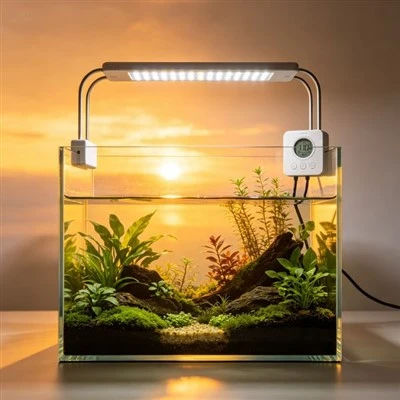
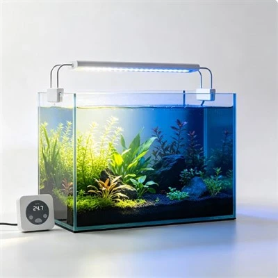
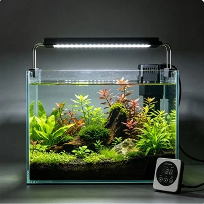
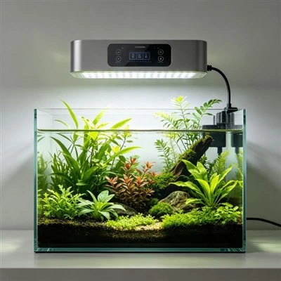
Imagine two aquarium bars that both receive 24 V at their external sockets. One bar includes onboard drivers for several channels. The other expects a particular controller that regulates current through a different topology. Swapping their supplies could lead to no output, unstable dimming, protection shutdown, or damage, depending on the designs. The example is not a prediction that every mismatch will fail in the same way. It shows why successful illumination during a brief bench check is not proof of electrical or thermal compatibility.
Troubleshooting should begin outside the sealed product. Record the exact fixture, hardware revision, approved supply, controller, connector, and observed symptom. Read input and output labels without confusing mains input with the low-voltage side. Restore only the documented power arrangement and normal settings. Keep ventilation paths clear and note whether the problem appears at startup, at one dimming level, on one channel, or after the fixture has warmed. Those observations give qualified service useful evidence without inviting an owner to probe live circuits.
Dimming adds another layer. Some drivers change current amplitude, some use pulse-width modulation, and complete products may combine techniques. A controller percentage is therefore not a universal current value and does not make drivers interchangeable. The driver must remain within its intended input, output, load, and thermal conditions across the allowed dimming range. Flicker seen on a phone video may also involve the camera's shutter interaction with modulation, so it cannot by itself diagnose a defective driver.
Thermal design is inseparable from current control. LED electrical behaviour and driver losses change with operating conditions, while excessive temperature can affect output and reliability. A replacement with an apparently similar current label may not fit the original heat path, enclosure, protection scheme, or control interface. Do not cover vents, change a thermal interface, or raise supply voltage to "push through" a dim condition. A higher-voltage adapter is not a safe cure for voltage drop or a driver that is entering protection.
Internal repair belongs to qualified personnel following an approved service process. Users should not bypass a driver, bridge protection, open a mains-powered supply, or substitute household wiring. If a unit has unstable output together with visible damage, unusual heat, smoke, moisture intrusion, repeated protective-device operation, or a burning smell, stop using it and disconnect only if that can be done safely. Keep the failed parts and labels available for examination rather than destroying evidence through informal modification.
Good service documentation identifies the complete approved power chain. It states the power-supply input, low-voltage output where applicable, polarity, connector keying, driver or controller relationship, compatible revisions, and permitted replacement assembly. Engineering records add load range, rated current, thermal conditions, dimming method, and protection response. This information does not encourage unsafe internal repair; it prevents a superficial label match from becoming a substitution decision. Aquarium LEDs need controlled current, but the practical unit of safety is the entire tested power and thermal system, not one component name.
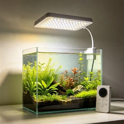
Dimming compatibility is another reason not to substitute by label. A driver may interpret an analogue signal, pulse-width command, digital bus, resistance, or manufacturer-specific control, and the permitted wiring and control range can differ. Connecting an unknown dimmer can lead to flicker, failure to turn fully off, unexpected current, or damage even if the supply voltage appears plausible. The approved driver arrangement includes its control interface and any protective or temperature-feedback behaviour, not just two output leads. Service records should name the complete replacement assembly and revision.
Thermal conditions influence what current regulation can safely deliver. A fixture may use temperature monitoring or power reduction to keep components within its design limits, while another system relies on fixed output and passive cooling. An owner should not defeat a fan, cover fins, or assume that a temporary brightness reduction proves a failed driver. Record the operating program, ambient condition, ventilation, and symptom, then follow qualified diagnosis. Manufacturers should verify current, output voltage range, protection response, dimming behaviour, and temperature under representative loads. These controls make the LED system repeatable; they do not establish a biological outcome or make an unapproved power source compatible.
Connector polarity, isolation, grounding arrangements, and enclosure requirements also belong to the approved power system. A replacement should match the documented electrical and mechanical interfaces, not merely illuminate the LEDs during a short bench trial. Brief operation cannot demonstrate safe temperature or protection behaviour.