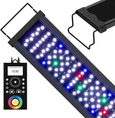
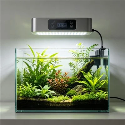
One dark patch in an otherwise operating aquarium light is a useful clue, but it is not a circuit diagram. From outside the housing, an owner may see six LEDs off on the left while the rest of the bar continues normally. That pattern could be consistent with a failed series string, a connector issue, a channel-control problem, driver protection, or another design-specific fault. The visible LED nearest the boundary is not automatically the failed component. A responsible diagnosis begins by recording the pattern and the exact product, not by guessing which part should be bridged.
LEDs are commonly arranged in series, parallel, or networks that combine both. In a simple series string, the same current passes through each LED in sequence. An open connection at one point can interrupt the path and darken the whole string. A shorted LED may allow current to continue while changing the voltage across the remaining string, but actual driver behaviour and protection determine the result. These examples explain possibilities; they do not predict every fixture, because manufacturers use different topologies, channel groupings, connectors, and fault responses.
Parallel branches behave differently. One branch may stop while another continues, or a shared driver may reduce output or shut down when it detects a condition outside its operating range. Current sharing can also depend on components that are not visible through the lens. In a combined network, the pattern seen from the aquarium may reflect several layers at once: LED board routing, cable connections, channel control, and driver protection. This is why a photograph of one dark LED cannot prove that replacing that LED alone will restore safe performance.
The first field check should preserve evidence. Record which physical sections are dark, which colour channels still respond, whether the failure is constant or intermittent, and whether it changes with an ordinary approved setting. Note the time since power-on, any recent move or cleaning, and whether the supply, controller, or cable is the specified one. Photograph the fixture label, batch or serial information, and the full illuminated pattern from a repeatable position. Do not open the housing simply to make the picture more "technical."
A normal controller check can sometimes separate a programmed state from a hardware symptom. If the manual permits it, select a known standard program and observe each channel from outside the product. A section that is dark only on one colour may follow a different circuit path from a section that is dark in every mode. Even so, external behaviour remains evidence for qualified service, not permission to disassemble a sealed or mains-powered unit. Resetting should wait until schedules, versions, and the original symptom have been recorded.
Imagine a bar with two separately driven branches. An open LED in the first series branch could darken that branch while the second remains illuminated. In another design, the driver might detect the open load and shut down a wider channel. Both outcomes are technically possible. The point of the example is to avoid reverse certainty: seeing half a bar lit does not reveal the topology by itself. Only controlled design information, approved tests, or qualified analysis can connect the visible pattern to the actual circuit.
Unsafe shortcuts destroy both protection and evidence. Bridging an LED with wire or foil, pressing on a live board, swapping an unknown driver, or defeating a current limit can expose other components to conditions they were not designed to handle. A fixture that resumes glowing after such a change has not been shown safe. If there is moisture inside, a charred area, melting, unusual heat, smoke, a burning smell, or repeated protective-device operation, stop using the product and isolate it only when that can be done safely.
Service design can reduce unnecessary waste without encouraging risky repair. A manufacturer may use approved replaceable modules, keyed connectors, accessible low-voltage assemblies, or clear fault codes, but those features must be documented for the exact revision. Replacement decisions should consider electrical compatibility, thermal interfaces, sealing steps, firmware or channel mapping, and the authority of the person doing the work. A module that fits mechanically is not necessarily an electrical substitute, and reopening a protected enclosure may require a validated restoration process.
For factory or laboratory analysis, the useful record links the failed pattern to circuit topology, driver response, connector layout, test condition, and component findings. A known-good comparison is meaningful only when the model, revision, supply, program, and method match. Analysts should preserve the as-received state before rework, because an intermittent connector or contamination mark can disappear during handling. The report should distinguish observed facts, confirmed causes, and parts replaced as a precaution instead of presenting them as the same category.
A dark section is only an initial diagnostic clue. Record what still works, preserve the original condition, use only normal external controls, and send the pattern with complete product identity to qualified support. Clear diagnostic guidance and approved modular service can make repair more proportionate. The safest conclusion is also the most technically honest: series and parallel arrangements explain why failure patterns differ, while the specific circuit and evidence determine what actually failed.
Visible mapping can still be surprisingly informative. Note whether the dark area follows one colour channel, one repeated segment, one connector-fed module, or a random group, and test only the normal scenes available from the controller. A channel that appears dark in a blue-heavy photograph may be operating at a wavelength the camera renders poorly, so confirm with direct safe observation and controller state rather than the image alone. If the symptom is intermittent, record whether it follows warm-up, gentle permitted cable movement, or a particular setting. These observations help qualified service choose between a control, connection, driver, or board investigation, but they never justify bridging an LED, bypassing protection, or applying external power to the string.