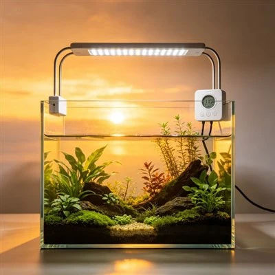
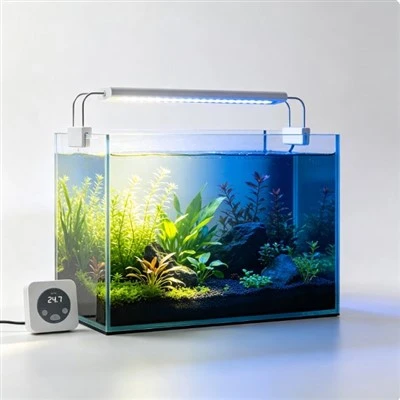
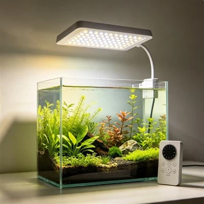
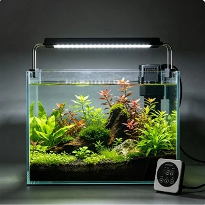
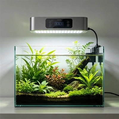
Two laboratories can test the same aquarium light and truthfully report different surface temperatures. One attached a sensor beside the driver; the other placed it several centimetres away on a cooling fin. Neither number can be interpreted until the location is known. Temperature varies across a fixture, and a thermocouple responds to conditions at its junction plus influences from attachment, wires, airflow, and nearby radiation. "The light reached 55 degrees" is therefore incomplete. Which part, measured how, under what ambient and operating condition, and at what time?
A thermocouple produces a thermoelectric voltage related to the temperatures of its measuring and reference junctions; the instrument may apply cold-junction compensation using the measured reference-junction temperature. It does not read an entire housing at once. Good contact with the intended surface is necessary, but the attachment method can change the very temperature being measured. A large blob of adhesive, thick tape, or metal clip may spread heat, insulate the point, intercept airflow, or contact a neighbouring feature. Sensor wire size and routing can conduct heat toward or away from the junction.
Location begins with an engineering question. A designer may need an LED-board test point, driver-case temperature, heat-sink hot spot, accessible touch surface, a point near a capacitor, or an ambient-air reference. These are not interchangeable. Internal component points can support design limits, while an accessible surface point may support a user-safety evaluation under another method. A thermal camera can help locate patterns, but emissivity, reflections, focus, and line of sight require control, and the image does not eliminate contact-sensor documentation.
Coordinates should be repeatable. "Near the centre" allows different technicians to choose different spots, especially on a finned or curved housing. An annotated photograph or drawing can specify the face, distance from physical references, and orientation of the junction. The procedure should state whether paint, coating, or a small prepared patch is involved. If the sensor is replaced after a run, the new placement needs verification rather than relying on the previous tape outline.
Ambient temperature is part of the result, not background decoration. A fixture at the same absolute surface temperature has a different temperature rise in a cool laboratory and a hot equipment room. Position the ambient probe where it represents the air entering or surrounding the product according to the method, away from direct light, hot exhaust, and unrelated drafts. Record room control, local airflow, fixture clearance, mount orientation, and nearby surfaces. An open bench and a tight canopy can produce different thermal conditions.
Operating state must be equally clear. Channel settings, input supply, control mode, fan state, warm-up time, water or no-water test geometry where relevant, and installed accessories can affect heat generation or removal. Define stabilization by a documented criterion rather than taking the reading whenever the clock reaches a convenient minute. Some control systems reduce output or change fan speed as temperature rises; those events should be recorded because the final temperature alone may hide how the fixture protected itself.
Attachment needs validation for the temperature range and surface. Suitable tape, cement, welded junction, or mechanical method depends on the material, access, electrical considerations, and required accuracy. Comparing the attachment against another method or conducting a sensitivity study can reveal bias. Calibration status of the thermocouple and reader, channel mapping, sample rate, and cold-junction compensation should be part of formal work. Extra decimal places cannot recover uncertainty created by a poorly attached sensor.
Owners should measure only points that are accessible and permitted by the instructions. Reaching into a powered enclosure, sliding wire beneath a cover, blocking a fan, or placing conductive sensors near live circuits is laboratory work, not routine aquarium care. If an external surface feels unexpectedly hot, output becomes unstable, plastic discolours, or an odour appears, disconnect the equipment safely and contact service. A household infrared thermometer may support an observation, but its reading depends on surface and geometry and should not be presented as an internal component temperature.
Product reports become much more useful with a small placement diagram. Identify the model and revision, sample orientation, each sensor type and coordinate, attachment material, ambient-probe location, input and lighting settings, airflow, stabilization time, and recorded values. Report both absolute temperature and ambient context where appropriate. When laboratories disagree, compare these details before assuming one instrument is wrong. Often the "dispute" disappears when everyone sees that the probes were answering different thermal questions.
Temperature data earns meaning through position. A thermocouple beside a driver, on the centre plate, and at the tip of a fin can all be accurate while describing three separate parts of one heat path. Consistent coordinates, a validated attachment method that minimally perturbs the measured point, controlled ambient conditions, and clear operating states turn those local readings into engineering evidence. The most credible thermal number is not the hottest or the lowest one; it is the one tied to a defined point, a validated method, and the decision it was intended to support.
Uncertainty analysis should include the whole placement process, not only the reader's calibration certificate. Reinstalling a sensor several times at the marked point can show sensitivity to contact and operator technique. Testing more than one product sample reveals manufacturing variation that repeated readings on one unit cannot. Wire routing, adhesive cure, data-acquisition resolution, and ambient stability may each contribute. Report an appropriate uncertainty or repeatability statement when the decision depends on a small temperature difference. If a design limit is approached, improve the method or margin rather than choosing the coolest plausible placement. The objective is a defensible thermal decision, not a favourable number produced by moving the junction a few millimetres.
Thermal maps should also follow changes over time, not only the final stabilized point. Warm-up curves can reveal delayed fan action or control transitions and let another laboratory compare equivalent moments. Sampling rate and start condition therefore belong with the placement diagram whenever transient behaviour affects the conclusion.